Background
One of the criteria that determines the quality of a 3D printed part is how accurately the printhead traces out the true shape of the part’s geometry. Since the motion of the printhead (called the toolpath) is determined by the printer’s stepper motors, a more accurate toolpath can be obtained by ensuring the stepper motors accurately reflect the true geometry of the part being printed.
Recently an engineer discovered that the electrical signals sent by the stepper motor controllers on the printer motherboard to the stepper motors contained “bumps” which cause the motors to produce tiny motion errors with the printhead. So he (or someone) designed a small circuit board that filters out these steps and that goes between the stepper motor controller and the stepper motor itself. He made this 9 1/2 minute video that shows the results of using the circuits: https://youtu.be/qYI9XlADed8. If you skip to 2:30 in the video you can see a direct comparison of the filtered and unfiltered stepper motor motion.
This blog page describes how all this works and shows the results of some initial testing.
The Problem
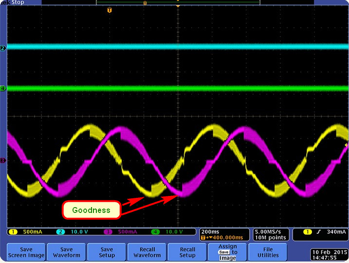
This photo shows a scope trace of the input and output wave forms of a typical stepper motor controller.

Notice the ugly corners in the output trace that differ significantly from the smooth shape of the input trace. These corners result in inaccurate movement of the printhead.
But after inserting the filter circuits between the stepper controller and the motor the results look like this:
Notice how much closer the output trace matches the input trace. This will result in a more accurate toolpath.
The Solution
I found the parts for this fix from a posting in the Facebook forum for my printer. They come from the Chinese website Aliexpress.com; here is a link to the item: Click Here. As you can see there is one circuit board for each of the X, Y, and Z stepper motors, and at a cost of less than $9.00 it is an inexpensive set of parts indeed.
Update: there is now an option to get 4 circuits for $10.00 at this link: 4 filters, but I don’t think there is much reason to filter an extruder stepper.
If you scroll down the Aliexpress page you’ll see a number of photos (including the ones above) that show results from using the parts. It took 16 days for me to get the parts, but that included 2 holidays.
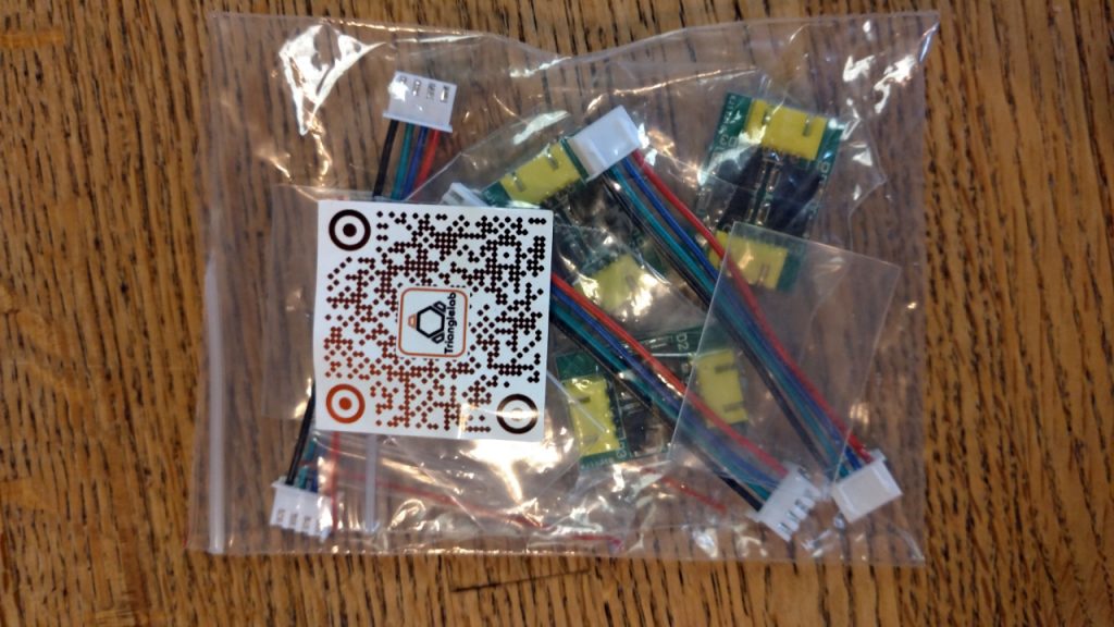
This is the parts package as it arrived:
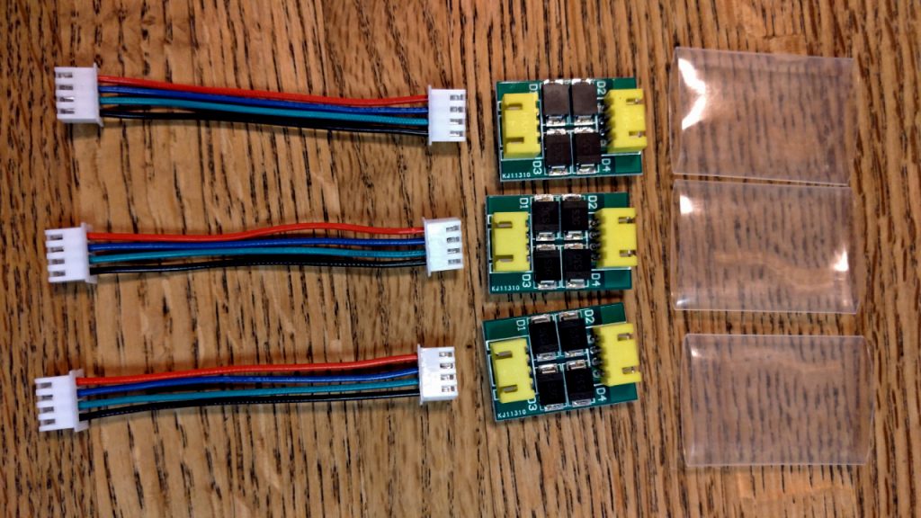
Here are the parts laid out ready for assembly. Note the clever plastic sleeves that cover the circuit boards after assembly.
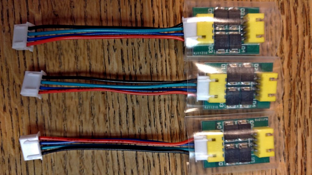
And here is everything assembled ready to connect to the motherboard.
Installation
Installing the filters is quite simple. I just unplugged my stepper motor cables from their connectors on the motherboard, plugged one of the filter connectors back into that socket, and then plugged the other connector into the stepper motor connector. Here is a photo if my motherboard before I started:
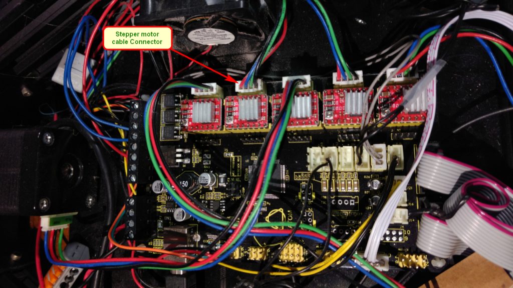
Note that my motherboard has 5 stepper motors because I did some Beta testing for a dual-extruder upgrade, and as a result my printer has 2 extruders.
Here is how the motherboard looks after connecting the filters:
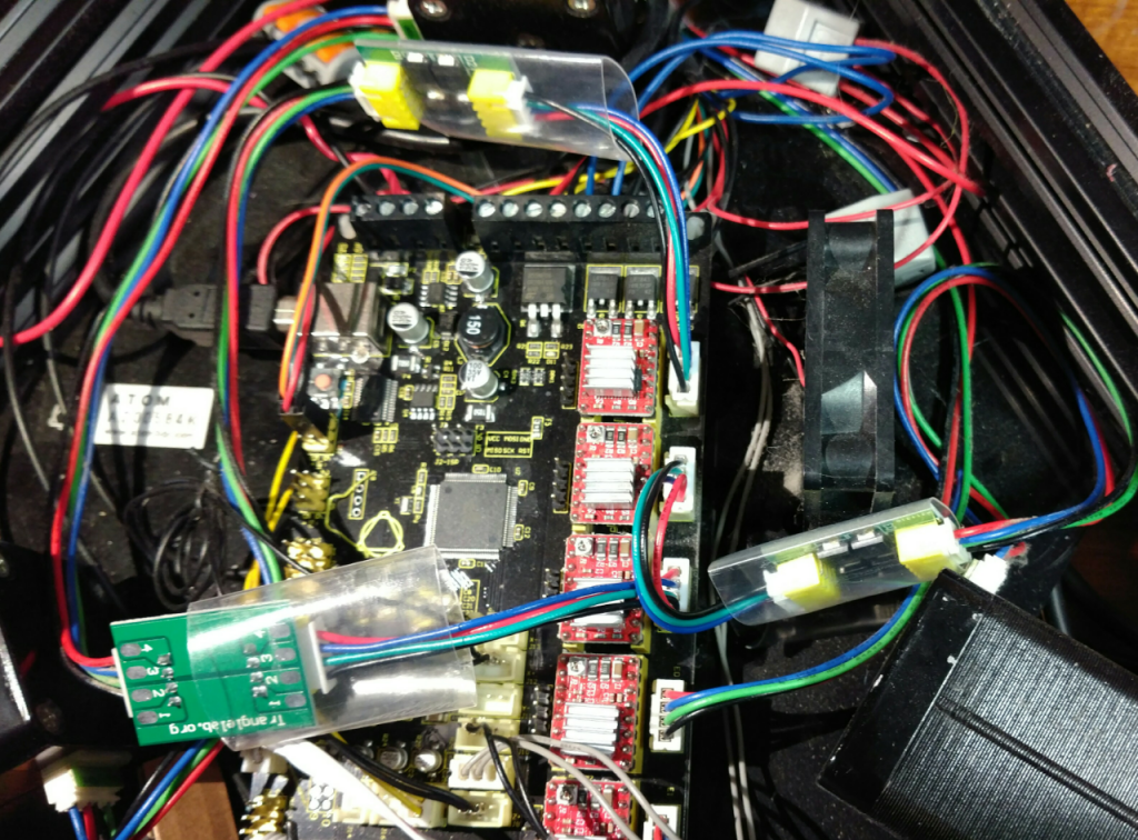
It is a bit more messy but still presents no problem reattaching the glass build plate.
Testing
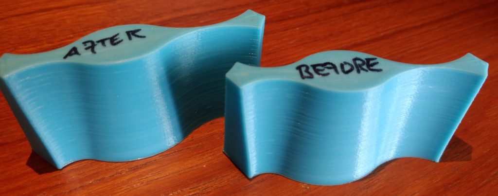
While I waited to receive the filters I created and printed a test part to check out the results. I also printed out the “torture test” part references in the YouTube video. As I expected, both of these printed with very good results:
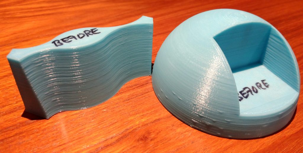
Of course, the proof is in the pudding. Here are the “After” results:
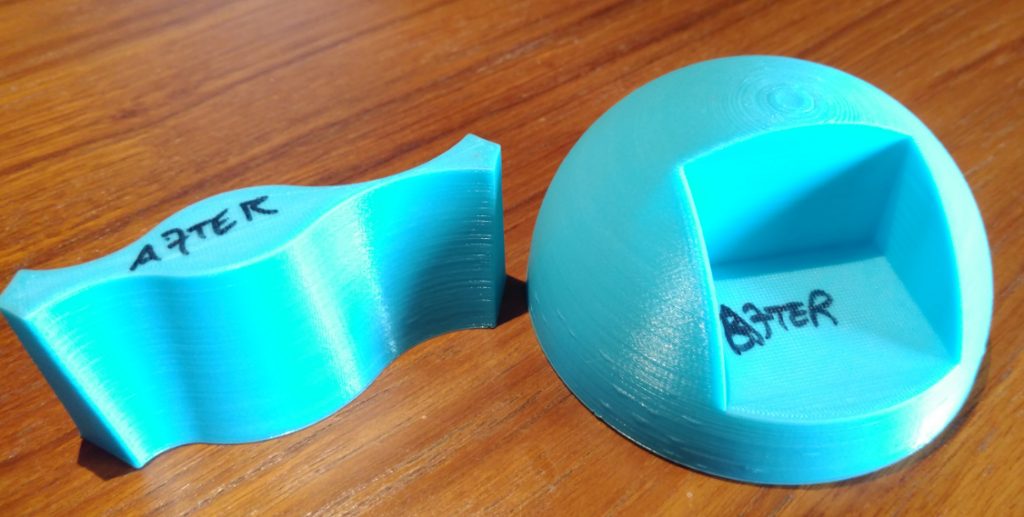
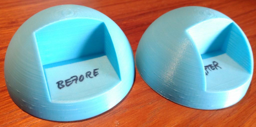
As you can see, there is not any significant difference. Here are the 2 torture test parts side by side:
And here are my 2 test parts:
Conclusion
This fix, as elegant as it may seem, appears to have no noticeable impact on parts printed by my printer. There may be a different result with a different printer, but someone else will have to determine that. What I plan to do is leave the filters installed for a few more prints and see if they have some positive effect on some other type of geometry. If that happens I will make an update to this page (or perhaps make a new one) that shows the result.
Update
Here is a copy of a message I received on the Facebook 3d printing group. It explains why I found no difference in the before/after tests shown above:
Chin Ming Keat hey, I am the guy that made the youtube video. ATOM uses high inductance motors (which is usually not the case for most hobbyist 3d printers) which don’t suffer from the issue mentioned in the video. Hence, you don’t see any differences with the before-after.